Jd Squared G1 Feed Rate Calculator
Powering on the Machine
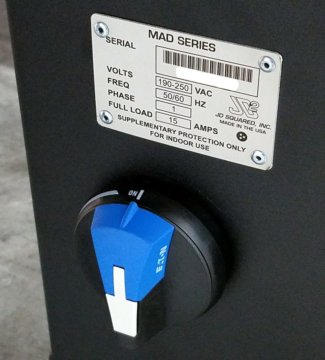
- Turn the disconnect switch to the on position.
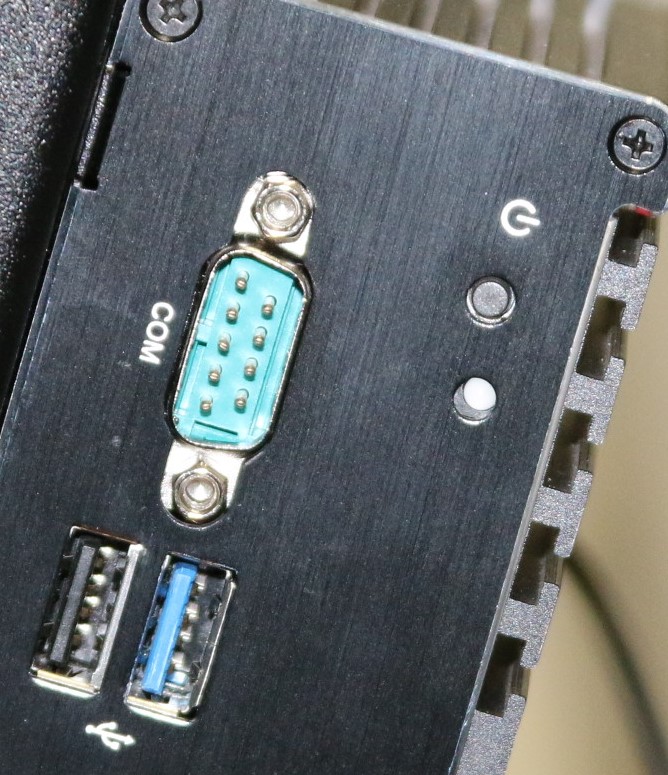
- Press the power button on the PC.
- Login when the PC finishes booting. The default credentials are:
| Username | Password |
|---|---|
| tech | Secure123 |
Powering Off the Machine
Shutting down the machine is slightly more complicated than powering on. Follow these steps to minimize the risk of data corruption in the controller:
- Close the MAD GUI program.
- Shutdown the PC computer
- When the computer completes shutting down, turn the disconnect on the control panel to the OFF position.
Configuring the MAD Control
The first time the MAD GUI software runs we are required to initialize settings, and verify that hardware connection choices (plasma unit, torch interface range, etc.) are set properly.
- Double click on the MAD GUI icon. This will initialize the controller and start the interface program.
- If the machine has not yet been initialized, you will need to select the "instance" by choosing the only one offered.

- Select your table size.
- After loading, you will see the main screen.
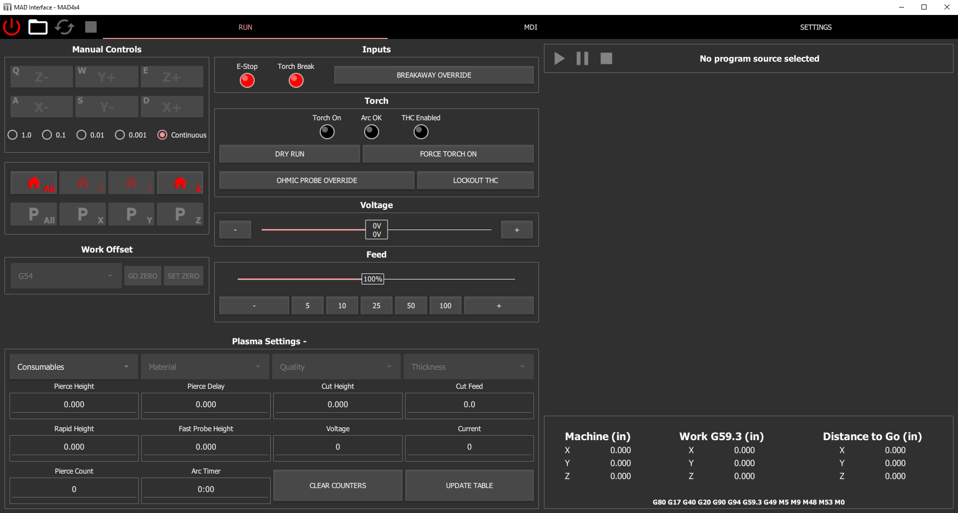
Note
The Plasma Settings in the center of the screen does not have a model displayed.
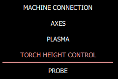
- Configure the torch interface settings. Navigate to the Settings tab and select Torch Height Control from the column on the left.
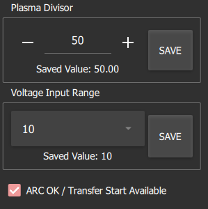
- Enter the Plasma Divisor , and select the Voltage Range from the combobox. Be sure to click the save button when changing values.
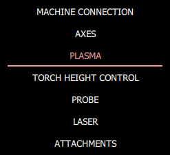
- Select Plasma from the left column.
- Click on Select Plasma Unit .
- Navigate to the plasma_units folder and select your model.

- Click the Write SheetCam Tool Files button, and select a destination directory for the tools. By default, we use the Documents->mad_tools folder.

- Close the MAD GUI program.
- Wait approximately 15 seconds to give the controller time to cleanup, and then restart the MAD GUI program. It will remember the settings chosen while loading, and when the main screen reloads, the plasma unit model will now appear in the center of the screen.
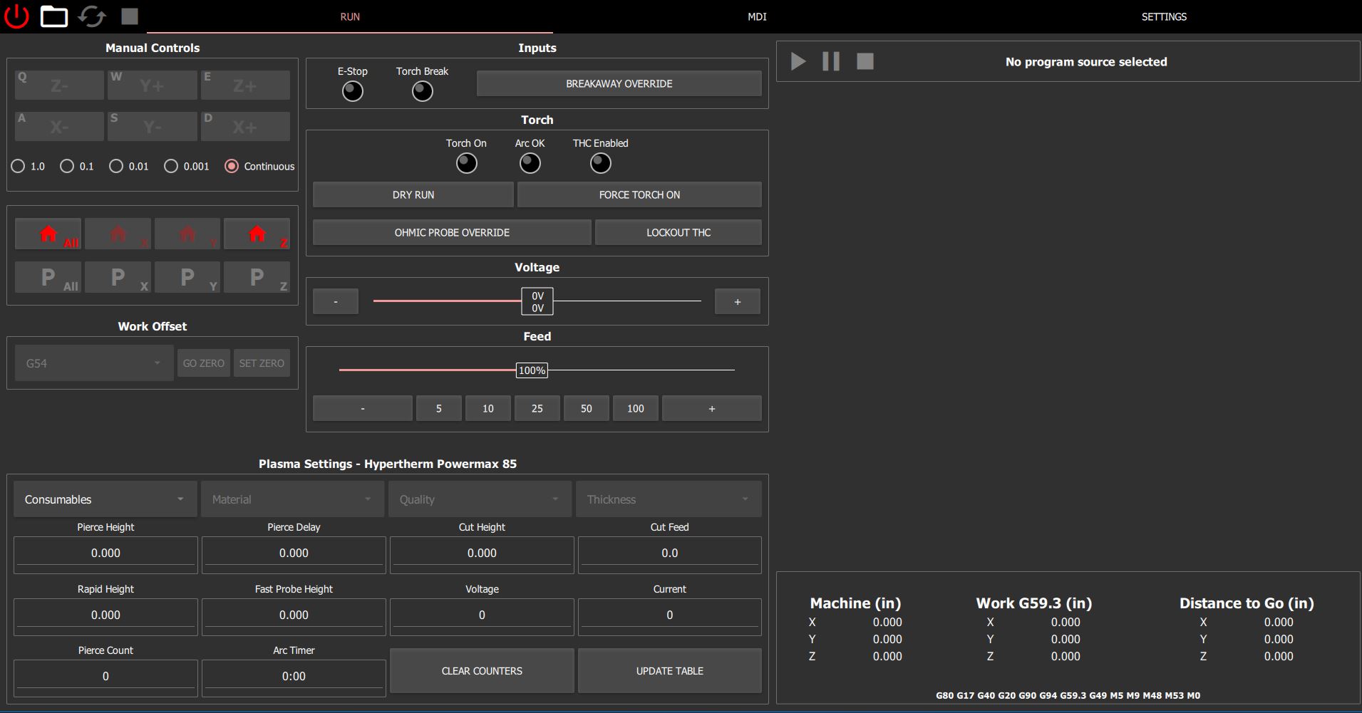
The Run Screen
Let's explore the components of the Run screen.
Main Toolbar

In order from left to right:
- Amplifier Power On - This is the operator's power control to the machine. It is also used to reset the machine in the case of an emergency (it will automatically turn off). The button states are:
| Color | State | Action when Clicked |
|---|---|---|
| Red | Amplifiers Powered Off | Try to reset any error and power on |
| Green | Amplifiers Powered On | Turn off the amplifiers |
Power Button Stuck Red?
If you click a Red power button and the button remains Red, there is an error condition that could not be reset. Check the Inputs to see if an emergency condition exists.
- Open Cut File - Use this button to select a new file for cutting.
- Control Default - Clicking this button will clear the machine state (G-Codes) back to their defaults.
- Global Stop - The stop button can be used in non-emergency conditions to abort motion / stop the currently running program.
Jog Controls
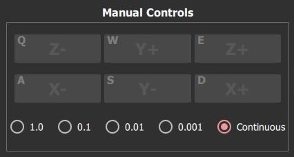
- Axis Jog Buttons - Pressing a jog button causes the machine to move along the indicated axis in the positive (+) or negative (-) direction at the Low Jog Speed . To move quickly around the table, we instead use the keyboard. Each jog button has a small letter indicating the keyboard shortcut. The keyboard jog mode allows for speed modifiers.
Control your Jog Speed
- Press the shortcut key to jog at the low speed.
- Press the Shift , and the shortcut key together to jog the machine at medium speed.
- Press the Shift , Control , and the shortcut key to jog the machine at high speed.
The default jog speeds are shown in the following table.
| Axis | Low Jog Speed | Medium Jog Speed (Shift) | High Jog Speed (Ctrl-Shift) |
|---|---|---|---|
| X | 5% | 50% | 1150 in/min (486 mm/s) |
| Y | 5% | 50% | 1150 in/min (486 mm/s) |
| Z | 5% | 50% | 300 in/min (127 mm/s) |
- Jog Increment Selection - Selecting Continuous allows for smooth jogging motion that responds to the operators key presses. Selecting a numeric increment, instructs the machine to move the given distance along the axis and direction chosen.
Incremental Jogging
You must press the jog button during the entire incremental motion command, or an abort is issued and the machine will stop jogging before reaching the expected position.
Homing and Park Controls
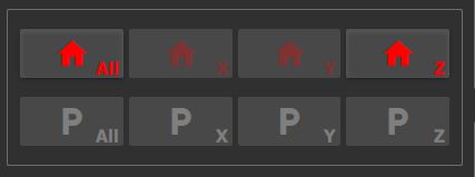
Homing Buttons - The row of houses represents each axis Homing commands and status. You may select a single axis to home, or simultaneously home all axes. As the machine changes states, the colors of the homing icons will change according to the following table:
| Home Button Color | Meaning |
|---|---|
| Red | Axis not homed |
| Green | Axis homed, and axis is at home. |
| White | Axis homed, but axis is not at home. |
Lost Power to the Servos?
If power is removed from the servo supplies, due to an emergency, or the operator clicking the amplifier power button, the motors lose track of their current position if the machine was in motion when the event occurred. You will always be required to home the Z-Axis after any power removal event, but the control does not strictly require you to rehome the X and Y axes. However, it is highly recommended that the operator rehomes all axes after any power loss event.
- Parking (P) Buttons - Enabled once the machine has been homed. Selecting one will rapidly move the machine to the park position for the axis selected which is X0.0 (left), Y0.0 (rear), or Z0.0 (up) in machine coordinates. If you choose to park all axes simultaneously, the machine will first park the Z-Axis, then park the X and Y axes using coordinated motion.
Work Offset Controls
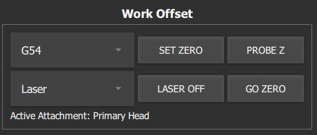
The Work Offset controls are used to select a working coordinate system, and set its relative origin in the working volume. When generating cutting code in the CAM software, we choose the relative location of the part to this zero point. All work offsets are saved to memory and persist across sessions.
- Current Work Coordinate Selection Box - Select the desired work coordinate system in this box. It defaults to G54 .
- Set Zero - Set the selected work coordinate's origin to the current location of the primary head (torch), or laser.
- Probe Z - Perform a Z-Axis height probe and save the result as the new Z-zero of the current work coordinate.
- Current Attachment Selection Box - Select the active attachment or laser indicator in this box. The Go Zero command respects this choice. When you select a new attachment, the machine will automatically reposition the tool.
- Laser Off/On - Controls the state of the laser indicator (on or off).
- Go Zero - Click this button to rapidly move the active attachment to the selected work coordinate's origin.
- Active Attachment Label - Displays the currently selected attachment.
Plasma Cutting?
To be compatible with the SheetCam post processor, the work coordinate G54 must be selected when plasma cutting.
Inputs

-
Emergency Stop and Torch Breakaway Indicators - If either of these indicators is highlighted, the machine cannot power the servo supplies. Clear the indicated condition, and then reapply power the servo motors.
-
Breakaway Override - Activate this button to instruct the machine to ignore a breakaway condition. After a breakaway, the Z-Axis is typically below the height required to remount the torch. By activating the override, the machine can be repowered and the Z-Axis can be rehomed. There is now sufficient height to attach the torch, and the breakaway circuit can be reactivated by turning off the override.
Warning
When Breakaway Override is activated the machine ignores the breakaway circuit. Motion will continue even if the head strikes an obstacle and falls away.
Torch Status and Controls

- Torch On Indicator - Lit when the machine control is asking for the plasma unit to turn on the torch. This signal will be simulated during a Dry Run , even though the physical torch will not be asked to turn on.
- Arc OK Indicator - Lit when the plasma unit asserts Transfer Start / Arc Okay signal. This signal is simulated during a Dry Run .
- THC Enabled - Lit when the Automatic Torch Height Controller is actively controlling the head.
- Dry Run Button - Click this button to activate or deactivate Dry Run mode. In this mode, the machine will move as commanded by the program, but the torch will not ignite. Since there is no arc voltage, the ATHC is also disabled and the machine will simulate the cut at Cut Height .
- Force Torch On Button - Asks the plasma unit to ignite the arc. Pressing this button when it is available will turn the arc on, even if the current running program does not have the torch enabled.
- Ohmic Probe Override Button - Activating forces the machine to ignore the Ohmic Probe and only use the Floating-Head Probe.
- Lockout THC Button - Activating manually disables ATHC.
On-the-Fly Voltage Control

The Voltage Control Slider displays both the measured Arc Voltage (top number), and the desired Cut Voltage (bottom number). Normal operation with ATHC enabled will force these voltages to be equal. Sliding the bar, or clicking the '+' and '-' buttons, adds an offset to the Cut Voltage allowing instantaneous adjustment of cutting height within a +/- 10V range.
On-the-Fly Feed Control

The Feed Rate Slider displays the feed override value as a percentage of the commanded feed. Valid feed overrides are between 5% and 200%. The numeric buttons below the slider quickly snap the feed override back to the percentage value indicated.
Program Display
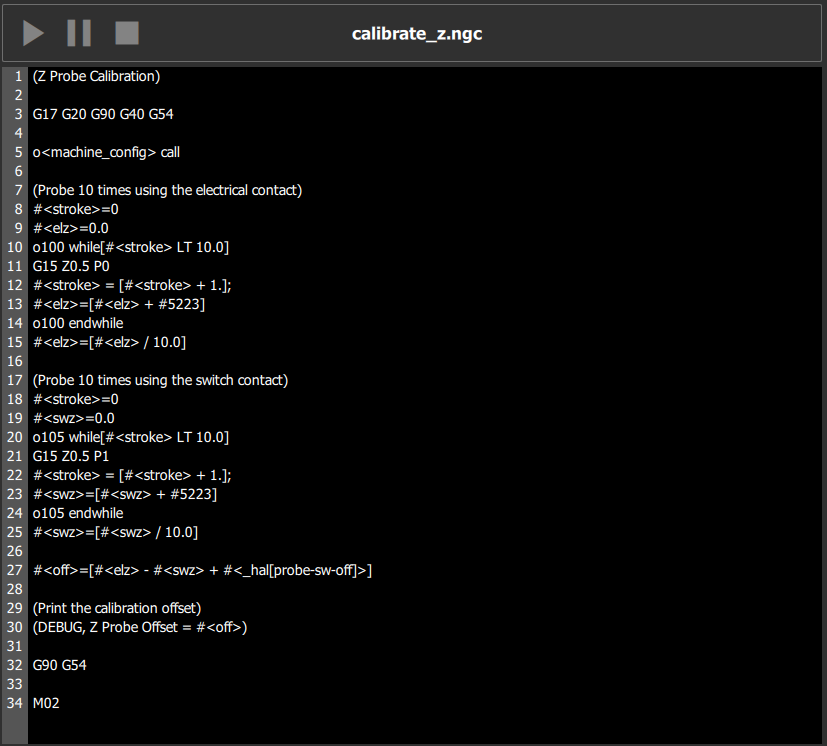
- Play Button - Start the current program from the beginning.
- Pause Button - Pause the current program.
Warning
Never pause the machine while the plasma torch is cutting and ATHC is active. Never pause during a probing operation.
- Stop Button - Stop the current action. This button is a duplicate of the global stop button.
- Program Display shows the current program loaded into the controller.
Current Commands Display

- Machine - The absolute position of the torch in Machine Coordinates
- Work - The absolute position of the torch relative to the active Work Offset
- Distance to Go - The relative distance left to complete the current move command.
- Control Status Label - Displays all modal commands active in the control.
Plasma Settings / Runtime Consumable Selection
Many of the settings required for successfully plasma cutting are stored in tables organized by Consumable Type , Material Type , Cut Quality , and Material Thickness . To access these values during operation we use the Plasma Settings control.

The top of the control allows progressively narrowing down the applicable cutting tables until the proper settings are found. You will pick these values depending on the material you are cutting from left to right (coarse to fine).
Left to Right!
If you select a new value in any of the drop-down boxes, you must also verify the choices in the boxes to the right of the change.
- Consumables Selection - Select the applicable consumable group, e.g., 45A Shielded.
- Material Selection - Select the applicable material, e.g., Mild Steel.
- Quality Selection - Select the cut quality. Higher number is better, but slower.
- Thickness - Select the material thickness. If the thickness you want to cut does not appear in the dropdown box, check other consumable groups. Certain consumables are not recommended for use with all material thicknesses. If the thickness of your material is in the range of materials displayed, but the value does not appear, select the closest material thickness as a starting point and manually adjust the settings after cutting test samples. If you would like to add the material as an available thickness permanently, see Editing Plasma Tables.
Editable Inputs
The remaining inputs in the control are editable at run time, and considered "hot". If you make a change directly to the box, the machine control will use it the next time the running program asks for the specific value. You can temporarily change a setting by simply typing a new value.
- Pierce Height - Height the plasma arc is started during the Piercing Phase.
- Pierce Delay - Time to wait after starting an arc before moving.
- Cut Height - Height during the Cutting Phase.
- Cut Feed - Traversal rate during the Cutting Phase.
- Rapid Height - Height the torch will move to after finishing a cut.
-
Fast Probe Height - Torch will rapid down to this height before IHD if:
- The material has been height detected at least once.
- The last height detection was within the programmable distance away from the current location. The default distance is 2" (50 mm).
-
Voltage - The desired Cut Voltage used by the ATHC
- Current - The required plasma unit current (amperage). This value is for reference only.
Current (Amperage) Setting
With Torch Interface Version 1, the operator must manually adjust the plasma unit to the correct setting!
- Pierce Count - The number of pierces performed by this consumable group.
- Arc Timer - The time the arc has been active for this consumable group.
Consumable Statistics
Each consumable group maintains its own pierce counter and arc timer. If you keep your consumables organized, you can track the age of multiple consumable sets simultaneously.
- Clear Counters Button - Clear the current consumable group's statistics.
- Update Table Button - Commit the current values to the permanent cut table and save the plasma settings file.
Here is an example of selecting consumables to cut 16GA mild steel:

The MDI Screen
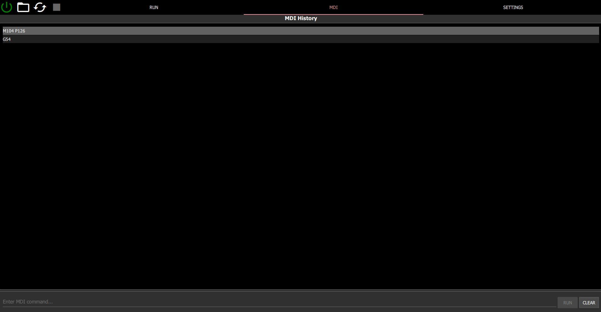
The Manual Data Input (MDI) screen is available to quickly issue direct G-Code commands to the controller without writing a program. It is not necessary for typical plasma cutting daily usage.
- MDI History List - A quick access list for previously issued MDI commands. To reissue a command, double click on the element in the list, or single click to select the line, and then click the Run button.
- Run Button - Execute the MDI command.
- Clear Button - Clear the MDI History List .
Settings Screens
Operator controllable settings are exposed through settings screens specific to each component.
Machine Connection Screen
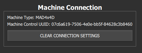
Displays the saved controller UUID (fingerprint) and machine type. If you accidentally select the incorrect machine type, click the Clear Connection Settings Button and restart MAD GUI to select again.
Axes Settings Screen
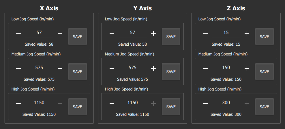
- Low Jog Speed - The jog value used when the axis is moved by clicking the jog button or using a key shortcut.
- Medium Jog Speed - The jog value used when the axis is moved by using a key shortcut and the Shift key.
- High Jog Speed - - The jog value used when the axis is moved by using a key shortcut, the Shift , and Control keys.
Torch Height Control Settings Screen
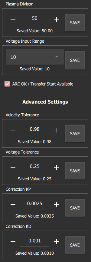
- Plasma Divisor - The voltage divider value selected in the plasma unit, e.g., 50 for a 50:1 divisor.
- Voltage Input Range - The voltage range selected on the Torch Interface.
| Voltage Range | Voltage Input Range Value |
|---|---|
| 0V - 10V | 10 |
| 0V - 20V | 20 |
| 0V - 300V | 300 |
- ARCOK / Transfer Start Available - Check this box if the plasma unit has a Transfer Start / Arc Okay signal available.
- Advanced - Velocity Tolerance - Factory setting, do not change.
- Advanced - Voltage Tolerance - Factory setting, do not change.
- Correction Kp - The velocity in inches / millisecond the ATHC is allowed to move.
- Correction Kd - A damping term for Correction Kp . The default factory settings are aggressive. They allow the ATHC to change the Z-Axis position at 150 in/min (63.5 mm/s). If this is too fast (head dips near lead-outs) consult the chart below for additional settings options.
| Application | Correction Kp | Correction Kd | Max Z Velocity |
|---|---|---|---|
| Default (Mix) | 0.0025 | 0.001 | 150 in/min (63.5 mm/s) |
| Relatively flat material | 0.001 | 0.0005 | 60 in/min (25.4 mm/s) |
| Low-Speed | 0.0006 | 0.0003 | 36 in/min (15.24 mm/s) |
| Steeply Corrugated | 0.005 | 0.0025 | 300 in/min (25.4 mm/s) |
Probe Settings Screen
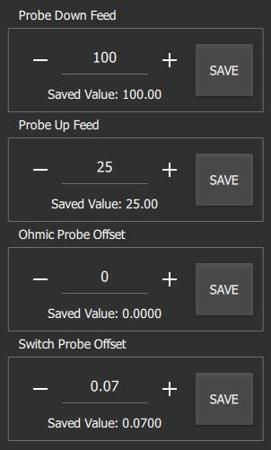
- Probe Down Feed - The velocity of the probe in the downward (search) stroke.
- Probe Up Feed - The velocity of the probe in the upward (latch) stroke.
- Ohmic Probe Offset - Factory setting, must be 0.0.
- Switch Probe Offset - Calibrated floating head offset found by running the calibrate_z.ngc program.
Laser Settings Screen
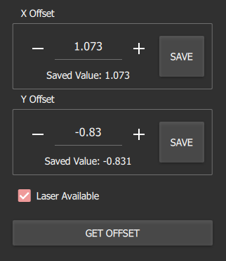
- X Offset - The X-Axis offset to the center of the laser indicator from the primary head (torch) position.
- Y Offset - The Y-Axis offset to the center of the laser indicator from the primary head (torch) position.
- Laser Available - Check if the machine has a laser indicator installed.
- Get Offset - Use the current position in work coordinates to set the X, and Y offset values of the laser.
Attachments Settings Screen
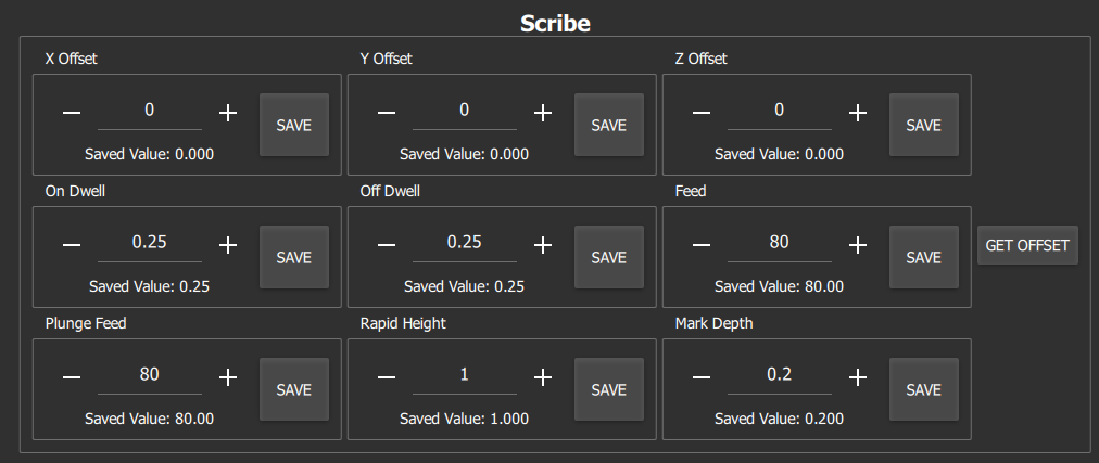
The attachment settings screen has multiple groups, one for each available attachment. The settings available for each attachment are:
- X Offset - The X-Axis offset to the center of the attachment indicator from the primary head (torch) position.
- Y Offset - The Y-Axis offset to the center of the attachment indicator from the primary head (torch) position.
- Z Offset - The Z-Axis offset to the center of the attachment indicator from the primary head (torch) position.
- On Dwell - The time in seconds (s) the machine waits before continuing after turning on an attachment.
- Off Dwell - The time in seconds (s) the machine waits before continuing after turning off an attachment.
- Feed - Traversal rate during a normal feed operation (marking, scribing, etc.)
- Plunge Feed - Traversal rate during a down feed (-Z) operation (marking, scribing, etc.)
- Rapid Height - Height the attachment will move to between marks.
- Mark Depth - Height the attachment will move to during a mark, scribe, etc.
- Get Offset - Use the current position in work coordinates to set the X, Y, and Z offset values of the attachment.
Source: https://support.jd2.com/MAD/MADGUI/
0 Response to "Jd Squared G1 Feed Rate Calculator"
Post a Comment